
Basics of Gaging
Gages are an essential part of the manufacturing industry, so it’s a good idea to understand the basics of gaging. Gaging is the process of measuring features on a part to ensure they are within the required tolerance. There are many types of gages, but the two main categories are readout gages and physical check gages.
Basics of Gaging – Tolerances
Not every gage needs to be made to the best tolerance possible. Gaging experts suggest using the 10% rule. This means that if the feature’s tolerance is +/-.001″ (.0254mm), the gage should be a class ZZ gage with a .0002″ (.00508mm) total tolerance. The tightest gage tolerance available is class XXX, which can be as tight as .000010″ (254µm). The tolerance assigned by each class changes based on the gage size. You can click on the link below to view our gage tolerance chart and see what class is best for you.
Gage Tolerances
Readout Gages
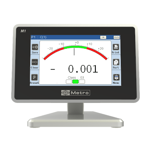
Readout gages measure the feature on a part that is being inspected. The gage (often a needle) is set to a certain dimension, normally by using a calibrated gage block. The part is then measured, and the readout will show how much larger or smaller than the gage block the part is. The readout can be analog or digital, and a pass/fail system can be implemented on the readout.
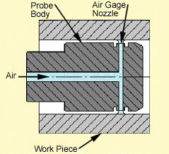
A more complex style of readout gage used in tool rooms is the air gage. This style of gage uses a gage form that fits over the part feature and forces air through the part. The air fills the cavity between the part and the gage, and the pressure is measured and displayed on a readout.
Physical Check Gages
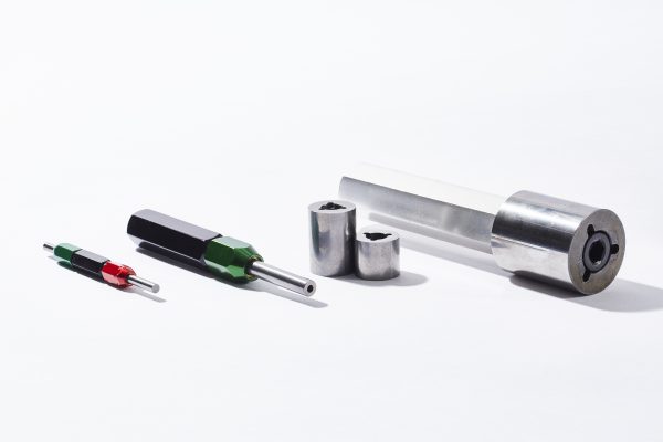
Go/No go gages are the most common type of physical check gages. They are the first type of gage to understand when learning about the basics of gaging. They involve two or three components – a “go” member, a “no go” (or “nogo”) member, and a handle. The way these gages work is simple; an operator fits the go member to the part, then the no go member. The go member should fit on the part, and the no go member should not fit on the part. If the go does not fit or the no go does fit, the part is out of tolerance.
These gages are very easy to use as there is no calibration required in use. The only calibration required is to ensure that the gages are still at the intended size. However, readout gages are more useful while a part is being manufactured. A skilled operator can see the size the part is at, and more quickly bring it into tolerance.
Mechanical Gages
In the machining world, the main types of mechanical gages used are micrometers and calipers. Micrometers are measuring devices mounted to frames to inspect linear dimensions such as OD and depth. Most micrometers can precisely measure to a thousandth of an inch. Calipers consist of two adjustable jaws used to measure the distance between two opposite dimensions on a material. Mostly calipers are used to measure thickness, ID, and OD dimensions. When comparing micrometers and calipers, micrometers are more accurate because they have the ability to measure very small dimensions. Calipers can measure to .1mm where micrometers can measure to .01mm.

Beyond the Basics of Gaging – Materials
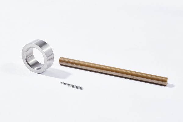
Material selection goes beyond the basics of gaging but is still important to understand. Hardened steel is the most common material used in gages due to its initial cost. There are many shops that can make X or XX gages in most sizes out of steel for less than $50. However, if longevity is required carbide is a much better material. It has up to 40x better wear life than steel, although the initial cost is higher than steel. Carbide can also hold a better surface finish and tighter tolerances than steel. Another material often requested for gages is ceramic. Ceramic gages are extremely resistant to scratching and will not corrode in the environments of humidity or other corrosive settings.
How GLE Can Help
GLE Precision has been a manufacturer of gages for decades. Our tolerances are as precise as .000003” [.0762µm] and are one of our core capabilities. Our equipment and expertise allow us to create custom gages with unique features as well as standard gages. When surface finish, size, or tolerance are critical, we look forward to the challenge of manufacturing to the customers’ needs.

